

A pool enclosure that tracks perfectly on the day of installation but starts binding, creaking, or sticking eighteen months later almost always has a groundwork problem, not a product problem. The aluminium frame above ground gets all the attention, but it is the 200mm of prepared substrate beneath the base channel that determines whether you get twenty years of smooth operation or a warranty dispute by year two.
This article follows the preparation sequence in the exact order it must happen on site: planning checks first, then measurement and site reading, then foundation selection, then surface preparation, right through to what the installation crew expects to find on the day they arrive. Skip a step or reverse the order and you create rework. Do it in sequence and the installation itself becomes straightforward.
Why the Ground Beneath Your Enclosure Matters More Than the Structure Above It
An aluminium pool enclosure does not spread its weight across a wide slab the way a house extension does. The entire structural load transfers to a relatively narrow perimeter footprint, typically the base channel running around the pool edge. That concentration of load means small deviations in level do not stay small. They create compounding stress at every joint, fixing point, and panel corner, and that stress accumulates with every thermal expansion cycle and every time someone pushes a retractable section along its track.
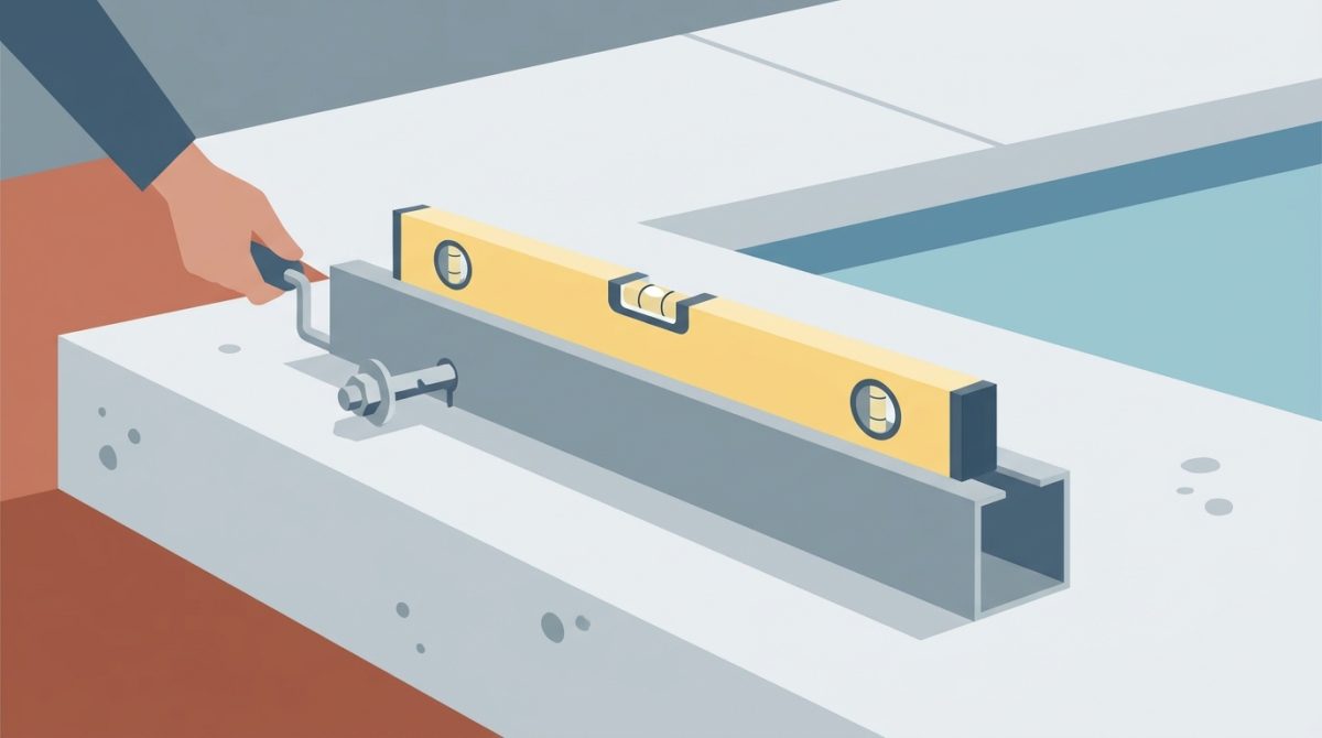
Retractable and telescopic systems are the most sensitive to this. They depend on parallel, coplanar tracks to slide correctly. A base that is out of level by as little as 10mm over 8 metres is enough to cause sections to bind mid-travel or, in worse cases, to derail entirely. That 10mm figure is not a worst-case scenario drawn from a single installation. It is a threshold that comes up repeatedly in enclosure maintenance call-outs, and it is well within the variation that an unprepared or informally laid patio surface can present.
The seasonal behaviour of UK soils makes this harder. Clay, which underlies a significant proportion of domestic gardens across England and the Midlands, is subject to seasonal heave of up to 25mm as it absorbs and releases moisture. A base that feels completely firm underfoot in August can shift enough between October and February to pull a track out of plane. The pool surround may look unchanged. The enclosure will tell you otherwise, usually through a section that suddenly needs more force to move, or a glazing panel that develops a persistent rattle.
There is also a straightforward financial argument for treating groundwork seriously. Poor foundation preparation is the leading cause of enclosure warranty disputes and early maintenance call-outs across the industry. A structural engineer’s assessment, a properly compacted sub-base, or a correctly specified drainage fall costs a few hundred pounds at most when done before installation. Remedial work carried out after the enclosure is in place, including lifting sections, re-levelling channels, and re-anchoring fixings, routinely costs several thousand pounds and voids installation warranties. The groundwork stage is genuinely the most cost-effective point in the entire project to spend time and attention.
Planning Permission, Permitted Development, and the Checks You Must Make First
In England, most domestic pool enclosures fall under Permitted Development rights, which means no formal planning application is required. But that general rule carries enough exceptions to make a quick check genuinely important before you spend anything on groundwork. Listed buildings require Listed Building Consent for any structure in the curtilage, regardless of size. Properties in Conservation Areas and Areas of Outstanding Natural Beauty face tighter restrictions on external additions, and the default Permitted Development allowances do not apply in the same way.
The cost of skipping this check is not abstract. A full planning application in England currently costs around £200 to £500. A pool enclosure installation costs £20,000 to £50,000 or more depending on specification. Being required to remove a structure at that price point because the correct permissions were not obtained is a documented risk, and it happens. The planning system does not make exceptions because the structure is attractive or because neighbours have not complained.
The most efficient first step is a pre-application enquiry with your local planning authority through the Planning Portal at planningportal.co.uk. A pre-application enquiry typically costs £100 to £250 and returns written guidance on whether your project needs permission and what constraints apply. That written response is worth considerably more than the fee if you ever need to demonstrate due diligence.
There is one specific dimension rule that affects enclosure selection directly. If the pool enclosure adjoins a boundary within 2 metres, the maximum permitted height under Permitted Development drops to 2.5 metres. Many mid-height and high-profile enclosure models exceed this. If your pool sits close to a fence or wall, you need to confirm the boundary distance before specifying an enclosure model, not after the order is placed.
Building Regulations generally do not apply to pool enclosures classified as temporary or non-habitable structures, and most aluminium enclosure systems are designed and specified to meet that classification. The important exception is electrical work. Any motorised drive system, automated cover mechanism, or external lighting circuit must comply with Part P of the Building Regulations, which covers electrical safety in dwellings. This means the electrical work must either be carried out by a registered competent person or notified to Building Control. This is not optional, and it affects the groundwork stage because conduit runs and any buried cable routes need to be planned before the base is laid.
Before any excavation happens, run a utility search. Contact LSBUD at lsbud.co.uk for a free buried services check. The search identifies the registered routes of gas mains, electricity cables, water pipes, and telecoms runs across your plot. Unregistered services also exist, particularly on older properties with previous extensions or outbuildings, so treat the LSBUD result as a strong guide rather than a guarantee, and use a CAT scanner or employ a ground investigation contractor if there is any doubt. Striking a service cable during foundation excavation is dangerous, expensive, and entirely avoidable.
Taking Accurate Measurements and Reading Your Site Conditions
Measurement errors at this stage cost nothing to fix. The same errors discovered on installation day cost time, labour, and sometimes materials. The goal here is to produce a site record accurate enough that it could be handed to the installation team without further explanation and they would encounter no surprises.
Start at the pool itself. Measure length and width at water level, not at coping stone edge. Coping stones vary in width and overhang, and the structural shell dimension is what matters for base channel positioning. To that dimension, add the manufacturer’s specified perimeter clearance. For Arch Enclosures aluminium systems, this is typically 150 to 200mm on each side to allow for the base channel width and its anchoring fixings. Measure this clearance on all four sides independently, as pools are not always as square as their specification sheets suggest, particularly older installations or those with irregular copings.
Pool features require separate measurement passes. Steps, ladders, handrail sockets, heat pump positions, and existing coping stones that project above the surround surface all affect where the base track can physically be anchored. A heat pump located against the pool wall on the long side, for example, may require the base channel to be offset or may necessitate a specific door or opening panel in the enclosure at that point. Capturing this at measurement stage means the enclosure design can accommodate it. Discovering it on installation day means the design cannot.
For level reading, use a long spirit level or hire a rotating laser level. Laser level hire runs approximately £40 to £60 per day from most plant hire companies, and for a project of this value it is money well spent. Walk the full perimeter of the enclosure footprint, taking a reading every 1.5 metres, and record the height difference at each point relative to a fixed datum, the top of a coping stone corner works well. Map these readings on a simple sketch. What you are looking for is the overall fall direction, any high spots that will need grinding or cutting, and any low spots that will pool water or need building up.
The threshold figure to know is this: a slope of more than 1 in 100 across the enclosure footprint needs corrective groundwork before installation. For reference, BS 8000-3, which covers workmanship on concrete substrates, recommends a minimum fall of 1 in 80 away from the pool edge for drainage purposes. So the target is a surface that drains adequately (at least 1 in 80 fall directed away from the pool) but does not vary so much across its total area that it places the base tracks out of plane. Achieving both at the same time is what proper sub-base preparation is for, and it is why reading the existing levels in detail matters before you decide what kind of foundation work is needed.
Alongside level readings, you need to understand what the ground is actually made of. A simple probe bar pushed to 600mm depth will tell you a great deal. Firm resistance with a granular feel indicates sand or gravel, which drains freely and is generally suitable for pad footings without additional treatment. Soft or sticky resistance that smears on the probe tip indicates clay, which requires deeper or wider pads to get below the active heave zone. Ground that gives way easily and inconsistently, or probing that turns up fragments of rubble, brick, or ash, indicates made ground, which requires a structural engineer’s assessment before any foundation design is finalised.
For a useful detailed reference on pool enclosure sizing before you begin these measurements, reviewing the specific clearance requirements for different enclosure heights and profiles will help you apply the right perimeter allowances from the outset.
Photograph everything as you go. Photograph the level readings marked on the surround, the probe locations, the coping stone condition, the position of any features that affect base track placement. Sketch the measurements on paper or a simple digital plan. The installation team will carry out their own survey, but discrepancies between your pre-visit record and their findings are caught and resolved at no cost if the documentation exists. Without it, disputes about what was known when become difficult to resolve and easy to delay.
Choosing the Right Foundation Type for Your Pool Surround
Not every pool surround calls for the same solution beneath it. The ground conditions, the enclosure model, and whether you are retrofitting around an existing pool or starting from bare earth all point toward different foundation approaches. Three methods suit most domestic pool enclosures in the UK: a continuous concrete strip around the perimeter, a series of isolated concrete pad footings at each anchor point, or direct anchoring into an existing reinforced concrete pool deck.
Continuous Concrete Strip
This is the most robust option and the preferred choice for heavier, high-profile enclosure models where uniform load distribution matters most. Dig a trench 300mm wide and 450mm deep around the full enclosure perimeter, or to the local frost depth if that is greater. Fill with C25 concrete, which is the standard mix for domestic structural applications in the UK. The continuous nature of the strip prevents differential settlement between anchor points, which is the thing most likely to cause aluminium tracks to rack or bind over time.
For a typical 8 metre by 4 metre pool enclosure, you are looking at roughly 24 linear metres of trench. At standard soil conditions that means around 3.2 cubic metres of concrete, which is comfortably within the capacity of a single ready-mix truck delivery.
Isolated Pad Footings
Where budget or access is a constraint, isolated pad footings offer a faster and cheaper route. Each pad should be 450mm by 450mm in plan and 300mm deep, poured at every track anchor point. Arch Enclosures’ track layouts typically space anchor points at 1.5 to 2 metre centres, so you will need to work from the exact layout drawings supplied before you dig anything. The critical point here is sequencing: get the drawings confirmed, set out the pad positions precisely, then pour. Pouring first and adjusting the track layout to suit misplaced pads is how projects go wrong.

Anchoring Into an Existing Concrete Deck
This is the most common scenario for retrofit installations where a pool already sits within a poured concrete surround. Before committing to this approach, check the deck thickness. Use a cover meter or ask a groundworks contractor to core a 50mm sample at a representative point. You need a minimum of 100mm of reinforced concrete to use standard expansion bolt anchors reliably. If the slab is thinner than that, switch to a chemical anchor resin system rated to at least 6 kN pull-out load, which is the minimum required to resist the uplift forces a loaded enclosure section can generate in wind.
One thing to check specifically on older pool decks: the reinforcement may be closer to the surface than current standards require, particularly on pools built before 2000. A cover meter reading of under 25mm to the nearest rebar means you need to adjust anchor positions or use resin anchors to avoid drilling into steel.
What to Avoid
Do not found an enclosure on compacted hardcore alone or directly on existing paving slabs. Base channels on a pool enclosure carry between 1.5 and 3 kN per linear metre under typical loading. Paving slabs are not designed to handle point loads at fixing centres and will crack or settle unevenly, pulling the track out of alignment. Hardcore without a concrete cap is worse: it compresses further every winter as frost cycles work on the voids.
Cure Time and Conduit Planning
In all cases, allow 28 days after pouring before bolting down any aluminium track. C25 concrete reaches approximately 25 N/mm2 compressive strength at 28 days at 20 degrees Celsius. Below 10 degrees Celsius the cure slows significantly, so winter pours may need a curing membrane or slightly longer wait. If you are installing a motorised telescopic enclosure, plan a cable conduit run from the mains supply point to the motor housing position before you pour. A 50mm diameter corrugated conduit buried in the concrete is simple and cheap at this stage. Chasing a channel into cured concrete afterwards adds cost and compromises the slab.
Levelling, Compaction, and Drainage: Getting the Surface Right
A foundation that is structurally sound but not level causes just as many problems as one that is too weak. Aluminium track systems are engineered to tight tolerances, and any deviation in the base surface feeds directly into how the enclosure panels align and how smoothly motorised or manual sections slide.
Checking Level After Cure
Once your concrete has reached full cure, check level across the complete perimeter using a rotary laser level set to a datum peg at one corner. The acceptable tolerance for aluminium track installation is plus or minus 3mm over the full perimeter length. That sounds tight, and it is. For a 24 metre perimeter, you are working within a 6mm total window from highest to lowest point.
If high spots exist, grind them back using a 125mm angle grinder fitted with a diamond cup wheel. Hire cost is approximately £50 per day, and for a typical perimeter you would expect to spend two to three hours on any localised high points. If low spots exist, do not just bolt down and shim. Build the surface up with a polymer-modified levelling compound rated to at least 25 N/mm2, such as Sika Monotop 612 or a direct equivalent. Standard self-levelling floor compounds are not suitable here because they are not rated for the sustained loads at fixing points.
Sub-Base Compaction for New Pours
If you are laying new concrete rather than working with an existing slab, the sub-base preparation underneath it is what determines long-term stability. Use a vibrating plate compactor, available to hire for £60 to £80 per day, on a minimum 100mm layer of Type 1 MOT hardcore. Make two passes in each direction, not just one. The target before pouring is a maximum settlement of 5mm under a 50kg point load. If you press a steel plate and a 50kg weight into the compacted surface and see more movement than that, add more hardcore and compact again.
Clay subsoils need particular attention. Clay moves seasonally as it wets and dries, and even a well-compacted hardcore layer over clay can shift over a winter. On clay sites, increase the hardcore depth to 150mm and consider a geotextile membrane between the natural ground and the hardcore to prevent clay fines migrating upward and reducing compaction over time.
Drainage Planning
Drainage is not optional. Water pooling beneath or around the enclosure base channel does two things, both bad: it accelerates corrosion at the aluminium-to-concrete fixing interface, and it contributes to frost heave under isolated pad footings in hard winters. The pool surround surface should fall at a minimum gradient of 1 in 80 toward a channel drain or soakaway. That equates to 12.5mm of fall per metre, which is barely visible to the eye but enough to move surface water reliably.
On sites with poor natural drainage or on clay ground, install a 100mm perforated land drain in a gravel-filled trench around the outer edge of the enclosure footprint. Connect it to the nearest surface water drain or soakaway. This is a half-day job for a groundworker and costs relatively little compared to the remedial work required if the ground beneath the enclosure becomes waterlogged. You can find more detail on how poor drainage contributes to frame deterioration in this article on pool enclosure mistakes.
Sealing the Surface
Before any track is bolted down, seal the top surface of new or existing concrete with a penetrating silane/siloxane sealer. These products work by lining the capillary pores within the concrete matrix rather than forming a film on the surface, which means they do not peel or wear away under foot traffic. The benefit is twofold: moisture ingress into the slab is reduced, and the reinforcement steel beneath is better protected from the chlorine-laden damp air that is a constant presence around any pool. Apply with a brush or low-pressure sprayer and allow to cure for 24 hours before proceeding. This is a small step that meaningfully extends the service life of the foundation beneath what is, in the end, a significant long-term installation.
Preparing the Site on Installation Day: What the Team Expects to Find
By the time the installation crew arrives, the groundwork decisions are behind you. What matters now is that the site is organised so the team can work efficiently and without creating problems for the finished enclosure.
Access and Working Space
Clear a minimum 1.5 metre working corridor around the entire enclosure footprint before anyone arrives. Installation crews handle aluminium extrusions that are typically 6 to 12 metres long, and they need unobstructed linear runs to manoeuvre sections into position without catching glazing panels on garden furniture, fencing, or plant pots. A section of glazing damaged because there was a garden ornament in the way is an avoidable cost that falls squarely on the homeowner’s side of the responsibility line.
Move anything that cannot be cleared in under five minutes the day before, not on the morning. Planters, stored equipment, children’s outdoor toys, and irrigation pipes along the pool edge are the typical culprits. If there is a gate or side passage through which sections must be carried, measure it against the extrusion lengths specified in your order documentation.
Pool Water Level and Equipment Positions
Keep the pool at its normal operating water level on installation day. A drained or partially drained pool temporarily alters the ground pressure against the pool shell walls and can cause very slight deck movement, particularly on older pools with flexible waterproofing membranes. It is a small effect but one that can introduce a millimetre or two of track misalignment in a system assembled to tight tolerances.
All pool equipment that will sit within the enclosure footprint, including heat pumps, filter housings, and chemical dosing units, should be in their final permanent positions before work begins. Moving any of these afterwards may require unbolting sections of base track, which adds time and risks disturbing the fixing torque on anchors that have already been set.
Marking Up and Power Supply
Mark the confirmed track centreline on the concrete surface with a chalk line or a strip of self-adhesive installation tape. The installation team will verify this against their drawings, but having it pre-marked reduces the set-up phase and signals that the site has been properly prepared. It also gives you a final opportunity to spot any discrepancy between the drawn position and the physical reality of the pool edge before the first anchor goes in.
Ensure a 240V mains supply is available within 10 metres of the site for the power tools the crew will need. For motorised enclosures, a dedicated 240V circuit with RCD protection should already be in place and routed to the agreed motor position, with the conduit you buried during the foundation pour accessible and labelled. If the electrical work has not been completed by a Part P registered electrician before installation day, the motorised system cannot be commissioned on the same visit, which means a return trip.
Soft Landscaping and Organic Material
Remove any soft landscaping, bark chippings, pebble mulch, or loose gravel within 500mm of the base track line. These materials compact unevenly under foot traffic during installation and trap moisture against the underside of aluminium extrusions once the enclosure is in place. Sustained moisture contact at the base of an aluminium profile, particularly where the alloy meets a concrete anchor or a steel bolt, is the starting point for galvanic corrosion. Keeping organic material away from the track perimeter from day one removes that risk entirely.
Common Groundwork Mistakes and How to Avoid Them Before It Is Too Late
Most foundation problems with pool enclosures do not come from ignorance. They come from impatience, from assumptions carried over from other building projects, and from small oversights that only reveal themselves on installation day. By that point, fixing them costs far more than preventing them would have done. Here are the mistakes that appear most often, and exactly what to do instead.
Pouring Concrete Before You Have the Track Layout Drawing
This is the single most avoidable mistake in the entire process, and it still happens regularly. A homeowner gets keen, the groundworker has a free slot, and the concrete goes down before the manufacturer has issued the anchor bolt layout drawing. The problem is that isolated pad footings need anchor bolts positioned within 5mm of the specified coordinates. Aluminium track sections are machined components, not flexible shapes you can nudge to fit.
If the bolts land in the wrong place, re-coring hardened concrete to shift a fixing by even 20mm is a half-day job. You need a diamond core drill, you risk cracking the surrounding slab, and you then have to re-fill the redundant hole with a structural epoxy before drilling again. On a typical enclosure with 12 to 16 anchor points, even two or three misaligned bolts will push remedial costs into the hundreds. Wait for the drawing. It takes a few days to arrive and it costs nothing.
Assuming an Existing Patio Is Level
Many patios are laid with a deliberate fall to drain surface water away from the house. That fall is typically between 1 in 60 and 1 in 80, which sounds minor until you do the arithmetic. Across a 6-metre enclosure width, a 1 in 60 fall means one side of the base track sits 100mm lower than the other. Even a modest 1 in 80 fall across 2.4 metres produces 30mm of difference, enough to throw the whole structure out of square and prevent the sliding sections from running true.
Always carry out a laser level survey before you commit to a foundation type or an installation method. If a fall exists, the solution may be a packer system under the base track, a localised screed to bring one side up, or a re-think of the track routing. None of those options is expensive if you identify the problem at survey stage. All of them become expensive if you find out during installation.
Underestimating Concrete Cure Time
Concrete reaches roughly 70 percent of its design strength at 7 days, but it does not reach full structural capacity until 28 days have passed. Fitting aluminium base track onto concrete that is less than a week old and torquing expansion anchors to the manufacturer’s specified 25 Nm is a genuine risk. The anchor is pulling against uncured paste rather than hardened matrix, and you can draw the bolt out without realising it has failed until the track shifts under load.
If your programme is tight and waiting 28 days is not realistic, use a fast-cure C30 mix with an approved accelerating admixture. Products in this category can reach the equivalent of 28-day strength in 7 to 10 days, depending on ambient temperature. Confirm with your concrete supplier before ordering, and get the data sheet in writing so you have a record if questions arise later.
Forgetting Conduit Routes for Motorised Systems
A motorised enclosure needs power routed to the drive unit, and that cable has to come from somewhere. The time to plan that route is before the concrete is poured, when laying a 20mm or 25mm HDPE conduit costs almost nothing. Once the base is set and the enclosure is installed, the options shrink sharply. Surface-mounting trunking along the base track looks poor and collects debris. Lifting sections of base channel to retrofit a conduit adds cost and downtime, and risks disturbing the anchor torque settings you carefully applied during installation.
Even if you are installing a manual system now but think you might add a motor later, lay the conduit anyway. Seal both ends with a pull-wire inside so it stays clean, and mark its position on a site sketch you keep with the building records. The conduit costs a few pounds. Forgetting it can cost several hundred.
Neglecting to Check for Underground Services After Landscaping Changes
An original utility search carried out at planning stage reflects what was in the ground at that time. Gardens change. A homeowner who added a low-voltage garden lighting circuit, a secondary irrigation feed, or a new garden tap after that search may not connect those additions to the enclosure groundwork. The cable or pipe is now exactly where you intend to excavate or drill.
Before any mechanical excavation, carry out a fresh service detection sweep using a cable avoidance tool (CAT) and signal generator. If you are not confident operating one yourself, hire a groundworks operative who is. The cost is small. Striking a buried cable or pipe is not just an expensive repair, it is a safety incident.
Leaving a Gap Between the Base Channel and the Concrete Surface
Base track needs to sit flush against the concrete it is fixed to. Any gap wider than 2mm creates a channel where water collects, algae establishes itself, and the track flexes fractionally under the load of sliding enclosure sections. Over a season or two, that flex works the anchor bolts loose and the track alignment drifts.
Before sliding the first enclosure section into position, run your hand along the underside of the base channel and check for daylight between the aluminium and the slab. Where you find a gap, fill it with a non-setting butyl mastic sealant rated for outdoor aluminium-to-concrete joints. Non-setting is the key specification here: a rigid sealant will crack as the aluminium expands and contracts through the year, reopening the gap. Butyl mastic stays flexible, keeps water out, and costs under a pound per metre. It is the simplest detail on the entire job, and it is often the one that gets skipped.
Getting these details right before the installation team arrives means the day runs to schedule, the structure performs as designed, and you are not revisiting the groundwork six months later wondering what went wrong. The foundation is invisible once the enclosure is standing, but it is the reason the enclosure keeps working year after year.
