
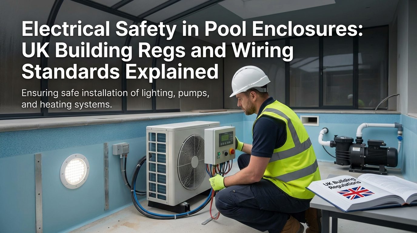
A standard outdoor pool is already a demanding electrical environment. Add an aluminium enclosure over it and you concentrate humidity, trap condensation, and bring conductive metalwork into continuous proximity with every circuit serving the water. That combination changes the risk profile considerably, and it changes the compliance obligations that go with it.
Most installation errors in pool environments are not the result of ignorance about electricity in general. They come from treating a pool enclosure like a damp outbuilding rather than recognising it as a distinct category with its own dedicated section of the wiring regulations. Understanding that distinction is where safe, certifiable work begins.
Why Pool Enclosures Create a Distinct Electrical Hazard Category
Water reduces human body resistance from around 100,000 ohms when dry skin contacts a source, down to as little as 1,000 ohms when the skin is wet. At mains voltage, that difference is the difference between a mild tingle and a fatal shock. Poolside, where people are barefoot, wet, and often gripping metal ladders or handrails, the conditions for maximum conductivity are almost always present.
An enclosure makes this worse in one specific way: it keeps surfaces wet. Condensation forms on glazed panels, on the aluminium frame, on junction box lids, and on cable runs that would dry out quickly in open air. A component rated for occasional splashing behaves very differently when it sits in near-constant high humidity for months at a stretch.

The common shock sources in pool facilities include underwater lighting, circulation motors, junction boxes, hydrotherapy equipment, exterior pool lights, timer controls, heaters, and electrically operated covers. Each of these is routinely present inside a domestic enclosure. A fault in any one of them, without proper protection, creates a hazard that can affect every surface in the structure simultaneously.
That last point is the one specific to enclosures rather than open pools. An aluminium frame is a continuous conductive structure. If a fault current finds its way into one section of that frame through a poorly terminated luminaire cable or a pump casing with degraded insulation, it can travel the full length of the structure. Anyone touching the frame while standing in or near the water completes a circuit. Without systematic bonding and earthing, the entire enclosure becomes a potential shock source rather than a protective shell.
This combination of factors is precisely why BS 7671:2018+A4:2026 dedicates Section 702 specifically to swimming pools, paddling pools, and fountain basins. The general installation rules in other parts of the standard are not sufficient on their own. Section 702 exists because the physics of this environment demands a separate set of requirements, and no amount of good general practice substitutes for following them explicitly.
BS 7671 Section 702: The Zones That Govern Every Circuit Decision
Section 702 structures the entire pool environment into three zones, each defined by its distance from the water. The zone classification is not a rough guide: it determines which equipment is permitted, which IP ratings are mandatory, and where sockets and switches can legally be placed. Every circuit decision inside an enclosure should start with identifying which zone the relevant part of the installation occupies.
Zone 0, Zone 1, and Zone 2: What They Mean in Practice
Zone 0 is the water itself. Any electrical equipment installed here, typically underwater lighting, must operate on SELV circuits at a maximum of 12 V AC or 30 V DC. The transformers supplying those circuits must sit outside Zone 1 entirely. Zone 0 requires IPX8 ingress protection, meaning the equipment must withstand continuous immersion. There is no flexibility on this.
Zone 1 extends 2 metres horizontally from the pool edge and 2.5 metres vertically above the water surface. Inside a standard domestic enclosure, this zone covers most of the usable floor area around the pool. SELV circuits remain the preferred supply here. Certain fixed equipment specifically designed and rated for Zone 1 use, such as dedicated pool pump units and water heaters, is permitted, but general-purpose electrical equipment is not. The IP rating requirement here is IPX5, meaning protection against low-pressure water jets from any direction.
Zone 2 extends a further 1.5 metres beyond the outer boundary of Zone 1. In a modest-sized enclosure, this may be a relatively narrow strip near the end walls or at the access points. Standard fixed equipment is permitted here provided it carries at least IPX4 protection against water splashing from any direction. The reduced IP requirement reflects the lower likelihood of direct water contact, but it is still a mandatory minimum, not a suggestion.
Sockets, Switches, and the 3.5 Metre Rule
No socket outlet may be installed within Zone 1. Any socket placed in Zone 2 must be protected by a 30 mA RCD. The practical convention used by most NICEIC-registered contractors working on compliant enclosure installations is to position all general-purpose sockets at least 3.5 metres from the pool edge where the layout allows, keeping them clear of Zone 1 with a meaningful margin rather than sitting exactly on the boundary.
This matters more inside an enclosure than it does in an open pool setting, because the enclosed footprint is often compact. In a telescopic enclosure covering a 6-metre pool, for example, a socket positioned 2.1 metres from the edge technically falls in Zone 2, but any movement of the pool structure or temporary equipment placed near the water could bring it into effective Zone 1 territory. Designing to the 3.5-metre rule from the outset avoids any ambiguity.
The April 2026 Amendment and Existing Installations
The BS 7671:2018+A4:2026 amendment, which came into force in April 2026, updated the broader wiring regulations framework. One of its practical consequences for pool enclosure owners is that any significant alteration to an existing installation triggers a requirement to review Section 702 compliance across the affected circuits. Adding an enclosure to a previously open outdoor pool almost certainly qualifies as a significant alteration.
This is relevant to homeowners who installed a pool several years ago under earlier versions of the regulations and are now adding an enclosure for year-round use. The enclosure changes the environment around the electrical installation materially: humidity increases, ventilation patterns change, and the frame introduces new conductive metalwork that must be bonded. An electrician signing off the enclosure installation cannot simply confirm the new structure is earthed and leave the existing pool circuits untouched. The interaction between the two must be assessed and documented. You can find further context on enclosure compliance requirements for UK homeowners planning this type of project.
Section 702 applies to permanent and semi-permanent paddling pools with electrically powered pumps, heaters, or lighting just as it does to built-in pools. Inflatable paddling pools with no electrical equipment at all are exempt, but the moment a pump or lighting system enters the picture, the full framework applies. There is no simplified version for smaller bodies of water.
Earthing, Bonding, and SELV: The Three Pillars of Safe Pool Wiring
Getting the zone classifications right tells you what equipment you can use and where you can put it. Earthing, bonding, and SELV supply are the three mechanisms that make the installation safe when something goes wrong. Each addresses a different failure mode, and none of them can substitute for the others.
Protective Equipotential Bonding
Equipotential bonding eliminates the voltage difference between simultaneously accessible metal surfaces. In a pool enclosure, that means connecting pool ladders, handrails, the aluminium frame, water supply and heating pipes, pump casings, and any other accessible metalwork to the main earthing terminal using copper conductors of at least 4 mm squared cross-section. The objective is straightforward: if a fault energises one metal surface, every other metal surface the swimmer could touch at the same time is at the same potential. No current flows through the body because there is no voltage difference to drive it.
This is not the same as simply earthing individual pieces of equipment, though that is also required. Bonding specifically addresses the simultaneous contact scenario, which is the one that kills people in pool environments. A swimmer holding a metal ladder while touching the pool wall, or a child climbing out of the water while resting a hand on the enclosure frame, both depend on equipotential bonding for their protection.
Arch Enclosures manufactures its aluminium frame sections with pre-drilled bonding lugs at regular intervals, which allows an electrician to make clean, secure connections without drilling through the structural profiles. Drilling through anodised aluminium to create a bonding point is not just inconvenient. It removes the corrosion-resistant surface at exactly the point where a dissimilar metal conductor is attached, accelerating local degradation over time. Factory-specified lugs avoid that problem entirely and make the bonding network easier to inspect and test during maintenance visits.
SELV Supply and Safety Isolating Transformers
SELV, Separated Extra-Low Voltage, is mandatory in Zone 0 and strongly preferred throughout Zone 1. A SELV circuit is supplied by a safety isolating transformer that provides galvanic separation from the mains supply. The secondary winding is not connected to earth, and the circuit voltage is capped at 12 V AC. Even if the insulation on a Zone 0 luminaire fails completely, the maximum voltage available to drive current through a swimmer’s body is 12 V. That is not zero risk, but it is an entirely different order of magnitude from mains exposure.
The safety isolating transformer must be positioned outside Zone 1. For most domestic enclosures, this means siting it in a dedicated plant room, in a weatherproof enclosure mounted to the outer wall of the structure, or in a utility room with a cable run into the pool area. The transformer itself must carry a rating for continuous damp conditions. A transformer specified for a dry indoor environment will not perform reliably in the elevated humidity inside an enclosure, and a failed transformer in the plant room can leave pool lighting circuits either dead or, worse, falling back on an improvised supply that lacks the required separation.
RCD Protection and Device Type Selection
30 mA RCD protection is required for every circuit serving the pool area, regardless of zone. This is non-negotiable in BS 7671 Section 702 terms. What is worth careful thought, however, is the type of RCD selected when variable-speed pump drives or electronic heating controls are on the circuit.
Type AC RCDs detect sinusoidal AC fault currents. Many modern variable-speed pump motors and electronic thermostat controllers produce smooth DC components in their fault currents, which Type AC devices may not detect reliably. Type A RCDs respond to both AC and pulsating DC fault currents. NICEIC-registered contractors working on compliant pool enclosure installations routinely specify Type A as the default where any electronic control equipment is present on the circuit, rather than using Type AC and then adding the electronic equipment later.
After commissioning, a continuity test across the entire bonded network must be carried out and documented in the Electrical Installation Certificate. The acceptable result is a resistance of no more than 0.05 ohms between any two bonded points. If that figure is not achieved, the bonding connection at one or more points is inadequate, and the certificate cannot be issued. For homeowners considering the full scope of pool ownership responsibilities, the water safety habits that come with enclosure ownership extend well beyond the initial installation and into how the space is used and maintained day to day.
Lighting, Heating, and Pump Circuits Inside an Enclosure: Specification Choices That Matter
Getting the zone classification right on paper is one thing. Translating it into actual component selections and cable routes is where most mistakes occur, and where the cost of getting it wrong becomes very visible during an inspection.
Underwater and enclosure lighting
Underwater LED lighting running on 12 V SELV is the standard specification for Zone 0, and for good reason. At that voltage, even a fault condition cannot drive a lethal current through a swimmer. The detail that often gets missed, however, is the niche and conduit penetrating the pool wall. Both must be sealed with a purpose-made waterproof fitting rated IPX8, because water will track back along the cable by capillary action if the entry point is not properly sealed, carrying moisture directly into the transformer housing and causing early failure or a fault.
Above-water lighting mounted on the aluminium frame inside Zone 1 requires a minimum of IPX5 to handle the water jets that can occur during normal pool use. Many architects and pool designers now specify IP65-rated recessed LED strip fittings that sit flush within the glazing bar profiles of the enclosure frame. This approach eliminates exposed pendant fittings entirely, which is significant because pendant fittings collect condensation at the canopy junction, corrode at the terminal block, and are consistently the first point of failure in a pool enclosure lighting system.

Heating circuits and their boundaries
Pool heating circuits are a frequent source of specification errors because the zone boundary for the heat source is not always obvious on site. Whether you are running a heat pump, an electric immersion element, or control wiring for a gas boiler, all connections and control wiring must be treated as Zone 1 equipment unless you can demonstrate that the physical installation point lies outside Zone 1’s boundaries.
A heat pump unit sitting on a patio slab adjacent to the enclosure, but beyond 2 metres from the water edge, falls entirely outside Section 702 scope. That is worth knowing because it gives designers and installers genuine flexibility when positioning equipment. The key is documenting the measurement clearly on the as-installed drawings, so that a future inspector can verify the classification without having to re-examine the physical layout from scratch.
Variable-speed pump drives and RCD compatibility
Variable-speed pump drives are now common in well-specified enclosure installations because they cut energy consumption by up to 70 percent compared with a single-speed motor running at full load. That is a significant operational saving over a swimming season. The complication is that the switching electronics inside these drives generate harmonic currents, and those harmonics can cause nuisance tripping on standard Type AC or Type A RCDs, which are not designed to handle the waveform distortion involved.
The fix is straightforward: specify a Type F RCD, or an RCD with a short time-delay, on the circuit feeding the pump drive. This retains full protection against genuine fault currents while tolerating the harmonic load without spurious trips. It is a one-line change on the design specification that prevents a significant amount of frustration during commissioning and ongoing use. You can find further detail on pool electrical hazard sources that make variable-speed drive compatibility worth planning carefully from the outset.
Motorised enclosure panels
Motorised roof and wall panels, one of the features that makes a retractable enclosure genuinely useful through changing weather, typically use 24 V DC actuators or motors. At that voltage they sit comfortably below the SELV threshold of 50 V AC or 120 V DC, which means the wiring within Zone 1 is treated as straightforward low-voltage work rather than a high-risk installation. The one requirement that still applies is that the motor housing itself must carry the correct IP rating for wherever it is physically mounted, because the enclosure environment remains damp regardless of the operating voltage.
Cable selection throughout the enclosure
All cable runs inside an enclosure should use double-insulated armoured cable, or be run in IP-rated conduit rated for the zone they pass through. Surface-clipped single-core cables inside standard grey PVC conduit are not suitable here. The damp, condensation-laden environment inside an enclosure will degrade standard PVC conduit fittings over time, and an inspection under BS 7671 Section 702 will flag this as a non-compliance. Armoured cable also offers mechanical protection against accidental damage during cleaning, furniture movement, and the general use that an enclosed pool space sees year-round.
Commissioning, Certification, and Ongoing Maintenance You Cannot Skip
A correctly designed and installed pool electrical system that has no paperwork to prove it is a liability. The documentation produced at commissioning is not a bureaucratic formality; it is what protects the homeowner legally, financially, and physically for the life of the installation.
Part P notification and certification
Any new pool electrical installation, or any significant alteration to an existing one, is notifiable under Part P of the Building Regulations in England. That means the work must either be carried out by a registered competent person who self-certifies through their scheme (such as NICEIC or NAPIT), or submitted to the local authority building control department for third-party inspection before and after completion. There is no grey area here, and no informal route that satisfies the regulation.
On completion the installer must issue an Electrical Installation Certificate. Keep this document permanently alongside your pool enclosure file, not filed away with general paperwork from the build. Insurers handling a water damage or fire claim will ask for it, and conveyancers will request it during any property sale. Its absence creates delays and, in some cases, forces a full re-inspection at the owner’s expense. For a broader view of how electrical compliance fits into pool enclosure compliance more generally, the regulatory picture extends well beyond wiring alone.
Inspection frequency in a damp environment
An Electrical Installation Condition Report should be carried out every year for a domestic pool enclosure. This is more frequent than the standard five-year cycle recommended for dry domestic premises, and the reason is straightforward: the damp environment accelerates insulation degradation, causes terminal corrosion, and weakens the mechanical components inside RCD mechanisms at a rate that makes a five-year gap genuinely risky.
The PWTAG Code of Practice, while primarily aimed at commercial pool operators, recommends integrating electrical inspection into a structured technical operation plan. Domestic owners with larger or more complex enclosures benefit from adopting the same discipline, treating annual electrical checks as a scheduled event rather than something triggered only by a problem.
Seasonal checks before reopening
If your enclosure is closed over winter, the electrical systems need a structured check before reopening, not just a visual sweep. That check should include:
- Testing all RCDs using both the built-in test button and a calibrated RCD tester, to confirm trip times remain within the 40 ms limit at rated fault current
- Visually inspecting all bonding connections for green oxide corrosion, which indicates the connection is degrading and needs cleaning or replacement
- Confirming that IP-rated enclosures on junction boxes and cable entry points have not been left open after previous maintenance visits, which is one of the most common causes of insulation failure found during annual EICRs
These checks take an hour with the right equipment and the right person. Skipping them because the pool looks fine and nothing tripped last season is the reasoning behind most of the electrical failures that occur in pool environments. The failure mode is gradual, invisible, and then sudden. An annual check is the only reliable way to catch the gradual part before it becomes the sudden part.
